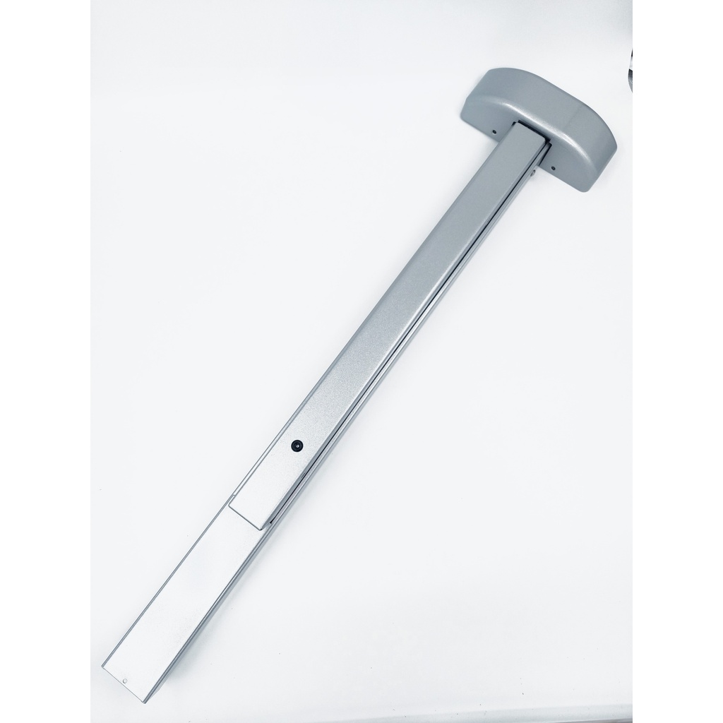
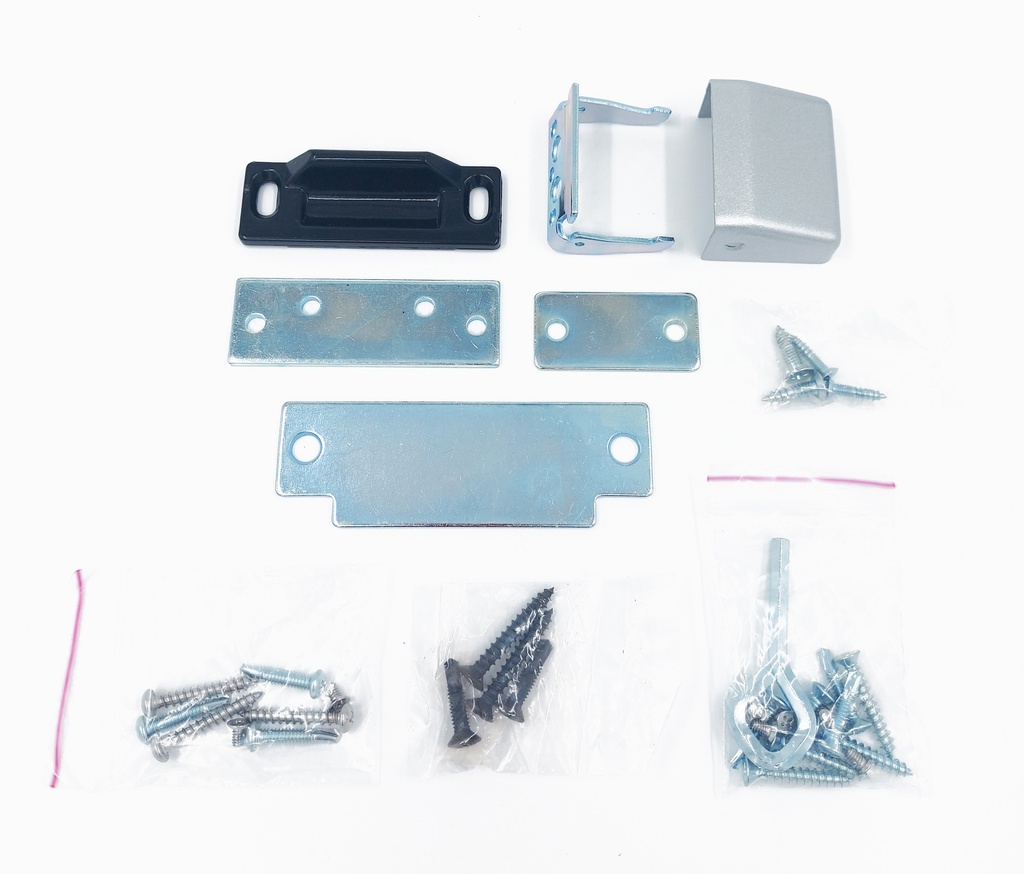
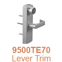
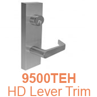
Dorex 9500 Series Panic Exit Hardware Rim Device 30–38" Door Width Aluminum Finish
9500PR3-28
Certifications
Certified ANSI/BHMA A156.3, Grade 1
UL listed, Panic Exit
UL listed, up to 3hr Fire Exit
5 Year limited warranty
Rail Assembly
Steel rail assembly
Stainless steel assembly (32D finish)
- Field sizable
Handing
Non-handed
Door Width
30–38" (762–965mm)
36–48" (914–1219mm) – option
Door Height
Panic Exit: 120" (3048mm) maximum
Fire Exit: 96" (2438mm) maximum
Door Thickness
1 3⁄4" (45.5mm)
2 1⁄4" (57mm) – available*
(*) Requires #9500KB363, see Parts & Accessories
Stile Width
4 1⁄2" (114mm) minimum
Measured from door edge
Projection
2 1⁄2" (64mm) from door surface
Latchbolt
Stainless steel, 3⁄4" (19mm) throw
Strike
9500PR: Steel, standard type #9500AS239
9500FR: Steel, standard type #9500AS245
Other strikes available
Dogging
For Panic Exit models only
Hex key dogging
Cylinder dogging1 – available
(1) See 9500 Trims & Accessories
Mounting
Machine and wood screws
Hardware
Sex nut & thru-bolts1 – available
Glass bead shim kit – available
(1) Included with 9500FR. Required for non-reinforced
hollow metal doors
Electrical
Electronic latch retraction – option
Options
Alarm kit – available*
Request to exit – available*
(*) Sold separately, see 9500 Trims & Accessories
Trims
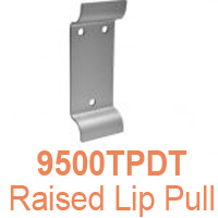
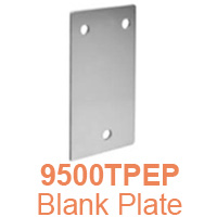
Lever, knob, pull, plate, escutcheon and handleset trims available
Sold separately, see 9500 Trims & Accessories
Finish
28–Aluminum, painted;
32D–Satin Stainless Steel
Other finishes available by special order
Product Page
9500PR/FR – 02.020
Trims & Accessories – 02.024
![]() 9500FR – Installation Instructions
9500FR – Installation Instructions![]() 9500PV – Installation Instructions
9500PV – Installation Instructions![]() 9500FV – Installation Instructions
9500FV – Installation Instructions
![]() 9500FL – Installation Instructions
9500FL – Installation Instructions![]() 9500AVFL (Fire Latch)
9500AVFL (Fire Latch)
![]() 9500AS251 (Overlapping Strike)
9500AS251 (Overlapping Strike)
Templates & Door Preparation![]() 9500PR – Main Chassis Template
9500PR – Main Chassis Template![]() 9500FR – Main Chassis Template
9500FR – Main Chassis Template
![]() 9500PV – Main Chassis Template
9500PV – Main Chassis Template![]() 9500PV – Top Chassis Template
9500PV – Top Chassis Template![]() 9500PV – Bottom Chassis Template
9500PV – Bottom Chassis Template
![]() 9500FV/FL – Main Chassis Template
9500FV/FL – Main Chassis Template![]() 9500FV/FL – Top Chassis Template
9500FV/FL – Top Chassis Template![]() 9500FV – Bottom Chassis Template
9500FV – Bottom Chassis Template
Templates & Door Preparation Trims & Accessories
Disclaimer
- We recommend that physical hardware be ordered and verified before starting any preparation, manufacturing or installation work.
- All product installations must be done by qualified personnel using the proper mounting hardware for the appropriate surface or material.
- We recommend that installers and manufacturers use the instructions inside the packaging provided by the manufacturer, as the manufacturer reserves the right to make technical changes, modify product or information without prior notice.
- Do not exceed the maximum weight or dimensions recommended by the manufacturer.
- All technical documents, drawings and instructions are provided as-is. Customers (primary or secondary) cannot derive any claim based on the use of these documents. No responsibility is or will be assumed.

